
|
|
| О школе |
|
|
The
corner cube reflector (CCR) is nothing more that three mirrors, forming a cube
corner (Fig.1). Then the outgoing beam has exactly the same direction as that
of the incoming beam. Why is it so? In order to understand this mathematically
we have to considewr reflection from a single mirror (Fig.2). Let
where
and all three mirrors are
orthogonal, i.e.,
This vector is directed
oppositely to
It means that the angle between Not only the CCR is a good retro-reflector. For example, a lens with a mirror in its focus is a perfect retro-reflector (Fig.3a).
a)b) Fig.3 A glass sphere embedded into a reflecting paint is also a good retro-reflector, but not a perfect one (Fig.3b). All road signs are coated with the paint, using this principle. 3. How good a reflector is the CCR? To answer this question we performed an experiment sketched in Fig.4.
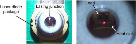
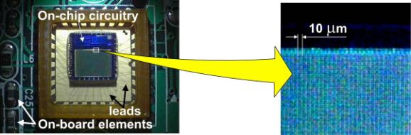
Fig.4 Laser pointer and the camera themselves are interesting devices, and we bet that very few people have ever seen the laser diode or the CCD matrix. For those willing to know how they look through the microscope Fig.5 and Fig.6 unveil this mystery. The pictures were taken with the help of the QX-5 digital microscope.
a)b) Fig.5. The 655 nm laser diode, slightly above the threshold. The laser beam carries only about microwatt of radiation. Magnification: a) 10× ; b) 60×.
Fig.6. Left picture is captured with 10× magnification, the right one - with 200×. The sensitive elements of the CCD matrix are visible. Their dimension is about 10×10 �m2.
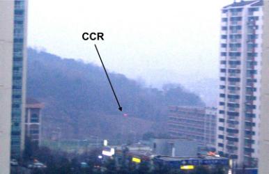
Although the laser beam is very narrow it carries only 3 mW of optical power. If there is any other reflecting surface instead of the CCR then we shall see no reflected beam at that long distance. But CCR makes it visible. To begin with, we purchased five CCR panels used to be installed on bicycles, and attached them to a stick as it is shown in Fig.7. The stick was installed at a distant hill seen from our window in Yeongtong, Suwon-City (Fig.8a). The view of our building from the hill is portrayed in Fig.8b.
a)b) Fig.8. The more complicated problem was to precisely aim the laser beam at the target. For this purpose we purchased a 12×40 Bushnell water-proof binocular, and attached a laser pointer to it (Fig.9).
With this system it turned out to be easy to direct the laser beam onto the CCR assembly and to make a photograph of the reflected signal. It is shown in Fig.10.
Fig.10. It is possible to conceive many other interesting experiments with this gadget, for example, to study the behavior of birds exposed to laser illumination. But this is already another story.
|
 ,
,